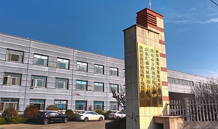

Leading the domestic modular building sector, we boast strong comprehensive brand strength and high recognition
Our product system covers various types of buildings, flexibly adapting to diverse usage scenarios
Our products are widely used in multiple fields, with outstanding practicality and adaptability
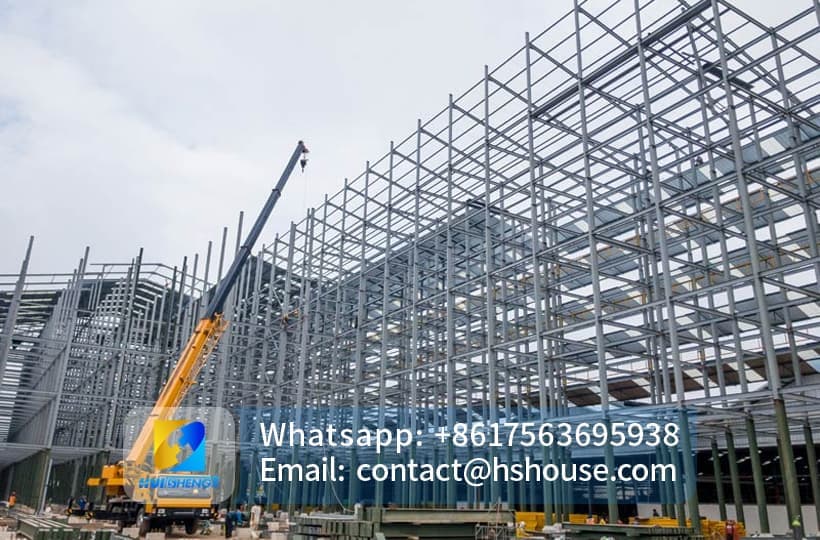
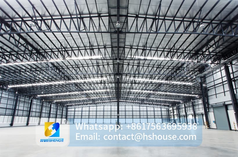
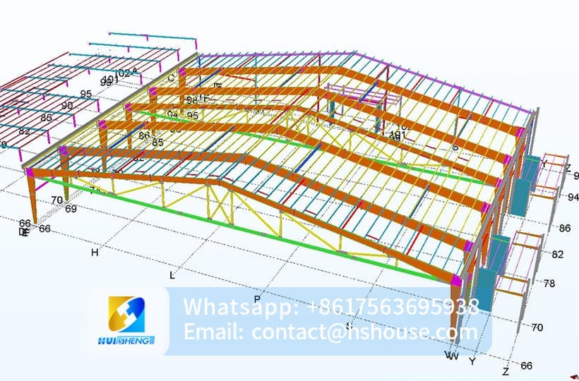
Custom Steel Structure Buildings for Industrial and Long-Span Projects
A successful steel structure project begins with the correct structural system—not simply with selecting the lowest price per square metre or the greatest amount of steel.
A warehouse, bridge, stadium, multi-storey building, space-frame roof, arch building and cable-supported structure are all made from structural steel, but they carry loads in different ways and require different engineering, fabrication, transportation and installation strategies.
Huisheng provides project-specific steel structure solutions covering:
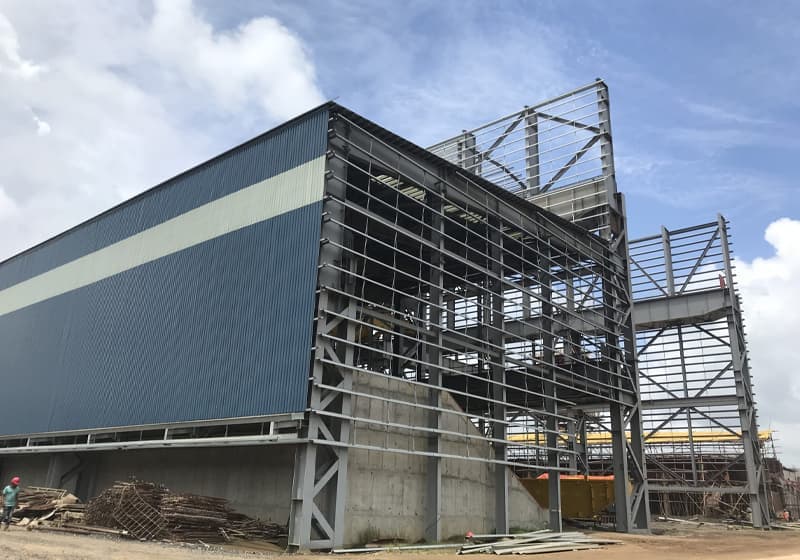
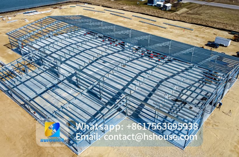
● Steel structure warehouses and workshops
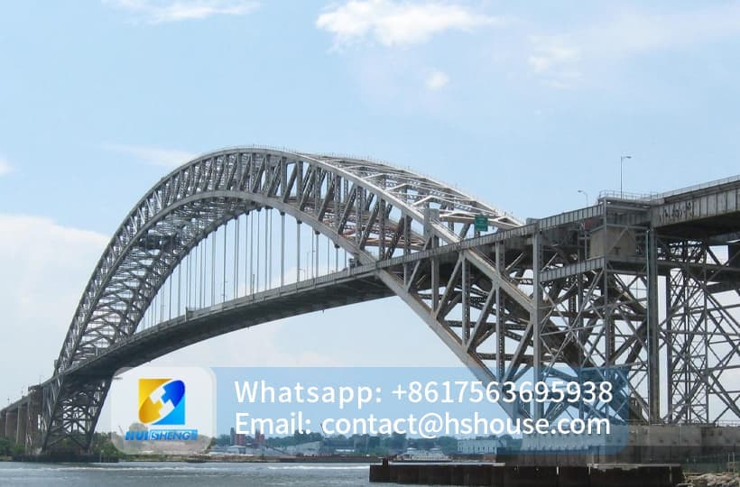
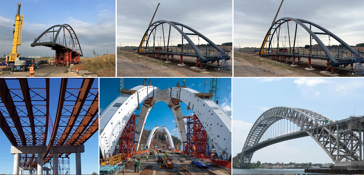
● Steel bridges and pedestrian bridges
● Steel stadiums and arena roofs
● Steel frame buildings
● Steel space frames and spatial structures
● Steel arch structures
● Steel cable and tension structuresStructural components can be fabricated in the factory while foundation and site work proceed at the project location. This parallel workflow can shorten the overall construction programme, provided that the design, connection details and anchor-bolt positions are confirmed before production. AISC identifies off-site fabrication and rapid erection as important advantages of structural steel construction.
Every project should be engineered according to its actual location, dimensions, loads, intended use, soil conditions, fire requirements, corrosion environment, transportation route and local approval process.
| Steel Structure Warehouse | Portal frame, truss or rigid frame | Logistics, storage, factory and workshop | Clear span, height, cranes and cost |
| Steel Structure Bridge | Girder, box girder, truss or arch | Roads, pedestrians, temporary crossings | Fatigue, transport, erection and durability |
| Steel Structure Stadium | Truss, lattice, space frame or cable roof | Stadiums, arenas and sports halls | Long span, sightlines and roof weight |
| Steel Frame Structure | Beam-column frame with bracing or moment connections | Offices, hotels, factories and multi-storey buildings | Floor layout, stability and service integration |
| Steel Space Frame | Two-way three-dimensional grid | Stadiums, terminals, exhibition halls and storage sheds | Column-free span and modular assembly |
| Steel Arch Structure | Curved compression arch or arch truss | Bridges, bulk storage and architectural roofs | Large clear span and horizontal thrust |
| Steel Cable Structure | Cable-stayed, suspended or cable-net system | Stadium roofs, canopies and landmark buildings | Lightweight span, pretension and movement control |
No single structural system is suitable for every project. Portal frames are frequently used for industrial buildings, while trusses, spatial structures, arches and suspended systems are selected where longer spans or more expressive forms are required.
A Steel Structure Warehouse should be designed around the buyer’s real operating process rather than treated as an empty steel shell.
The structural layout must consider:
● Required clear span
● Building length and width
● Eave height
● Storage-rack height
● Forklift and truck routes
● Loading docks
● Overhead cranes
● Mezzanine floors
● Production equipment
● Fire compartments
● Roof drainage
● Natural lighting
● Ventilation
● Future expansion
Portal frames are widely used for single-storey industrial buildings because they provide an efficient open interior and can be extended along the building length. Truss systems may be more suitable for longer spans, heavier suspended services or buildings containing crane systems.
● Logistics warehouses
● Distribution centres
● Production workshops
● Agricultural storage
● Cold-storage support buildings
● Aircraft or equipment hangars
● Vehicle maintenance facilities
● Manufacturing plants
● Construction-material warehouses
● Crane-equipped industrial buildings
This example is a reference project configuration, not a completed Huisheng case.
| Building Size | 60 × 120 m |
| Total Area | Approx. 7,200 m² |
| Clear Span | Two 30 m bays |
| Eave Height | 10 m |
| Structural System | Pre-engineered portal frame |
| Column Spacing | Approx. 6–8 m |
| Loading Area | Multiple truck loading doors |
| Roof System | Insulated metal roof with daylight panels |
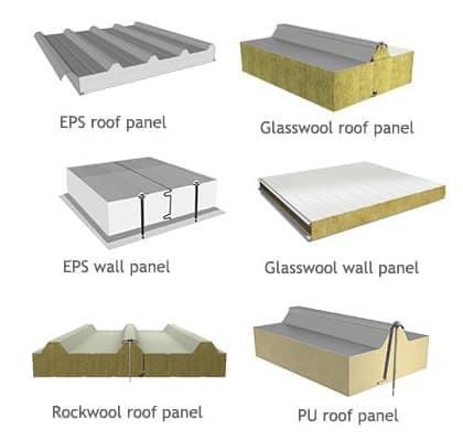
| Wall System | Insulated sandwich panels |
| Internal Equipment | High-bay storage racks |
| Future Requirement | Extension prepared at one end wall |
For this type of project, the engineering team should coordinate the column grid with warehouse racking, forklift aisles and dock positions before the steel weight is optimized.
● Overhead crane runway beams
● Mezzanine floor
● Office block
● Fire-rated partitions
● Insulated roof and wall panels
● Ridge ventilation
● Smoke vents
● Skylights
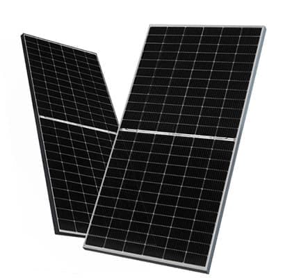
● Solar-panel support
● Canopies
● Loading docks
● Rainwater collection
● Future extension frame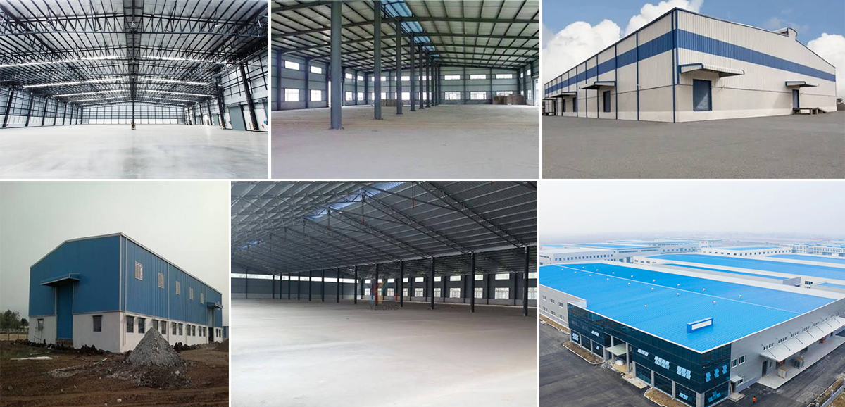
Steel bridges require a different engineering approach from steel buildings.
In addition to static load capacity, bridge design must consider:
● Repeated vehicle or pedestrian loading
● Fatigue
● Dynamic response
● Wind
● Temperature movement
● Bearing systems
● Deck interaction
● Corrosion protection
● Fabrication tolerances
● Transportation segment length
● Temporary erection conditions
● Inspection and maintenance access
Common systems include:
● Steel plate-girder bridges
● Steel box-girder bridges
● Steel truss bridges
● Steel arch bridges
● Modular temporary bridges
● Pedestrian bridges
● Cable-stayed bridges
● Composite steel-concrete bridges
The FHWA Steel Bridge Design Handbook treats material selection, fabrication, stability, fatigue, constructability and corrosion protection as essential parts of steel bridge design.
This example is a reference configuration.
| Total Crossing Length | Approx. 80 m |
| Main Span | Approx. 50 m |
| Deck Width | 4 m |
| Use | Pedestrians and bicycles |
| Structural Options | Steel box girder or steel truss |
| Deck System | Steel or composite deck |
| Fabrication | Factory-produced transport segments |
| Site Assembly | Bolted and welded segment connections |
| Corrosion Protection | Paint system or suitable protective coating |
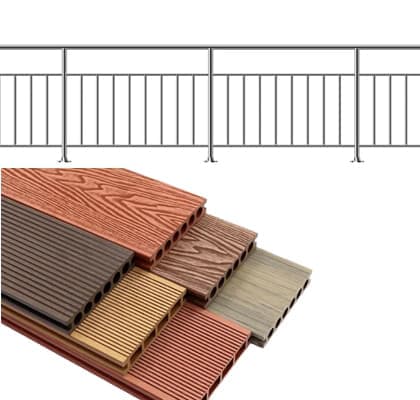
| Optional Features | Handrails, lighting, canopy and architectural cladding |
The bridge could be fabricated in several transportable sections, trial-fitted in the factory where required and assembled near the site before final lifting.
● Crossing length
● Span arrangement
● Road, railway or waterway below
● Deck width
● Vehicle or pedestrian loads
● Required clearance
● Applicable bridge code
● Corrosion environment
● Transport route
● Available crane positions
● Foundation and abutment responsibility
● Architectural appearance
● Installation restrictionsBridge fabrication should be coordinated with the project’s licensed bridge designer and the relevant transportation authority. A general building quotation is not sufficient for a bridge project.
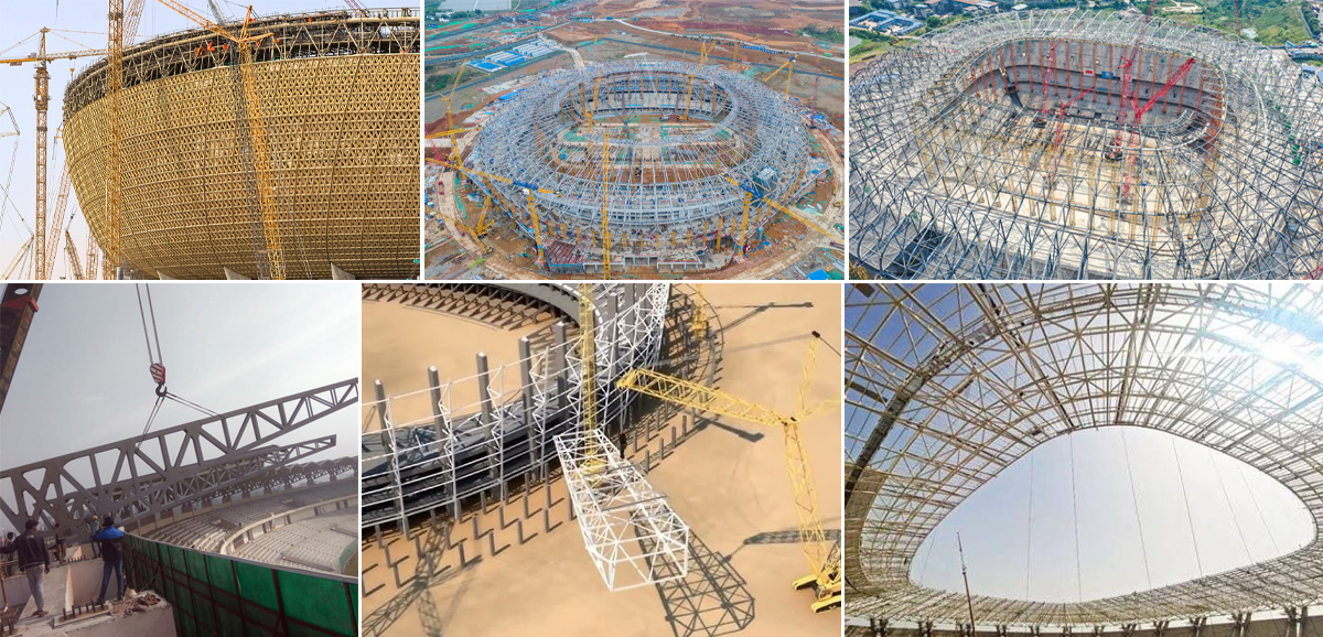
Stadium structures must provide large covered areas without obstructing spectator sightlines.
Common stadium systems include:
● Long-span steel trusses
● Cantilever roof trusses
● Steel lattice roofs
● Space frames
● Steel arches
● Cable-stayed roofs
● Cable-net and membrane systems
● Hybrid arch-and-cable structures
The selected system must consider:
● Seating-bowl geometry
● Column-free viewing
● Roof cantilever
● Wind uplift
● Drainage
● Lighting and scoreboards
● Acoustic equipment
● Maintenance walkways
● Roof cladding or membrane
● Construction sequence
● Temporary stabilityReal stadium projects demonstrate that different structural systems solve different requirements. Allianz Arena uses steel latticework for its roof, while AAMI Park uses a triangulated, shell-like steel roof system. Cable and tensile systems are also used for large-span stadium roofs.
| Stadium Capacity | Approx. 12,000 spectators |
| Roof Coverage | Main seating stands |
| Maximum Cantilever | Approx. 30–35 m |
| Structural Option | Cantilever truss or cable-assisted truss |
| Roof Finish | Lightweight metal or membrane roof |
| Main Services | Lighting, speakers, CCTV and drainage |
| Fabrication Method | Modular truss segments |
| Installation | Ground assembly followed by crane lifting |
| Architectural Requirement | Clear view with minimal front columns |
For this type of project, the truss depth and support positions should be coordinated with sightline studies and seating geometry before fabrication drawings begin.
● Grandstand canopy
● Full arena roof
● Retractable-roof support steel
● Space-frame stadium roof
● Cable-supported membrane
● Entrance canopy
● Spectator walkway
● VIP box steel frame
● Lighting towers
● Scoreboard support
● Maintenance catwalks
● Architectural exposed steel
Steel Frame Structures use columns, beams, bracing and connections to create the primary load-bearing skeleton of a building.
They are suitable for:
● Factories
● Office buildings
● Hotels
● Commercial buildings
● Schools
● Hospitals
● Parking buildings
● Multi-storey warehouses
● Equipment platforms
● Residential buildings
● Industrial pipe racks
The frame may use:
● Braced frames
● Moment-resisting frames
● Simple beam-and-column frames
● Composite steel-and-concrete floors
● Steel frames with concrete cores
● Truss-supported transfer levels
● Architecturally exposed structural steelStructural steel can provide relatively slender columns and flexible expansion possibilities, making it useful when internal floor space and future alteration are important.
| Building Height | Six storeys |
| Approximate Floor Area | 12,000 m² |
| Structural Grid | Approx. 8 × 8 m |
| Main System | Braced steel frame |
| Floor System | Composite or project-specific floor system |
| Ground Floor | Reception and commercial areas |
| Upper Floors | Offices or hotel rooms |
| Service Core | Stairs, lifts and utilities |
| Façade | Glass, metal panels or masonry-compatible system |
| Fire Protection | Project-specific fire-resistance system |
A successful frame design must coordinate columns with room layouts, parking spaces, corridors, façade modules and mechanical systems.
● Column grid
● Floor-to-floor height
● Floor vibration
● Vertical circulation
● Lateral stability
● Seismic design
● Fire protection
● Façade movement
● Service openings
● Floor loading
● Future extensions
● Architectural exposure level
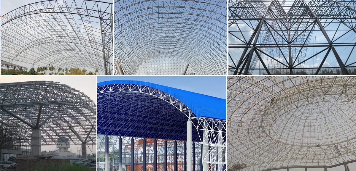
A Steel Space Frame is a three-dimensional system made from interconnected members that distribute loads in multiple directions.
Common forms include:
● Flat double-layer space frames
● Curved space frames
● Barrel-vault grids
● Dome structures
● Lattice shells
● Space trusses
● Multi-layer spatial structures
Typical applications include:
● Stadiums
● Exhibition halls
● Airport terminals
● Railway stations
● Shopping centres
● Swimming pools
● Aircraft hangars
● Coal-storage sheds
● Cement and mineral storage
● Industrial halls
Space frames are especially useful where a large roof must cover a wide area with few or no internal columns. The three-dimensional arrangement distributes loads through many connected members, while modular components can support factory fabrication and repetitive site assembly. Spatial steel systems are widely used for long-span halls and roof structures.
| Building Width | Approx. 90 m |
| Building Length | Approx. 150 m |
| Internal Columns | None in main exhibition area |
| Structural System | Double-layer steel space frame |
| Support Type | Perimeter steel or concrete columns |
| Roof Features | Skylights and suspended service zones |
| Ceiling Requirement | Exposed architectural structure |
| Installation Method | Ground assembly in sections or high-level assembly |
| Main Use | Exhibitions, events and conferences |
The space frame can be divided into repeatable modules, with each member and node numbered for packing and installation.
● Roof plan and curvature
● Clear span
● Support positions
● Suspended loads
● Snow and rain loads
● Wind uplift
● Drainage
● Skylights
● Mechanical equipment
● Fire requirements
● Architectural finish
● Installation height
cCrane availability
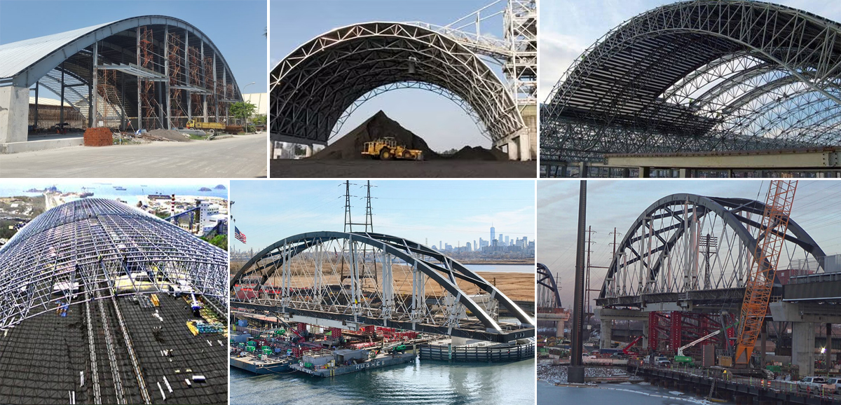
Steel Arch Structures transfer a large portion of the roof or bridge load through compression along a curved structural form.
Common configurations include:
Solid-web steel arches
● Trussed arches
● Tied arches
● Three-hinged arches
● Two-hinged arches
● Arch bridges
● Curved lattice arches
● Barrel-shaped storage structures
● Arch-supported roofs
Steel arches are suitable for:
● Bulk-material storage
● Coal-storage buildings
● Sports halls
● Aircraft hangars
● Railway platforms
● Exhibition buildings
● Pedestrian bridges
● Road bridges
● Architectural entrance structuresArch systems can create long column-free spans, but the designer must address horizontal thrust, support reactions, erection stability and geometric tolerances. SCI design guidance identifies arches and curved structures as established solutions for industrial and large-enclosure buildings.
| Clear Span | Approx. 70 m |
| Building Length | Approx. 160 m |
| Structural System | Steel arch truss |
| Main Use | Coal, minerals or agricultural materials |
| Internal Columns | None |
| Conveyor Clearance | Reserved along the centre line |
| Cladding | Corrosion-resistant metal sheet |
| Ventilation | Ridge or side ventilation |
| Installation | Arch segments assembled and lifted |
| Environmental Requirement | Dust and corrosion control |
The absence of internal columns allows loaders, conveyors and bulk-storage equipment to operate without structural obstructions.
● Span-to-rise ratio
● Support thrust
● Foundation reactions
● Arch bracing
● Buckling
● Wind uplift
● Uneven snow or material loading
● Corrosion environment
● Cladding connection
● Construction sequence
● Temporary supports
● Thermal movement
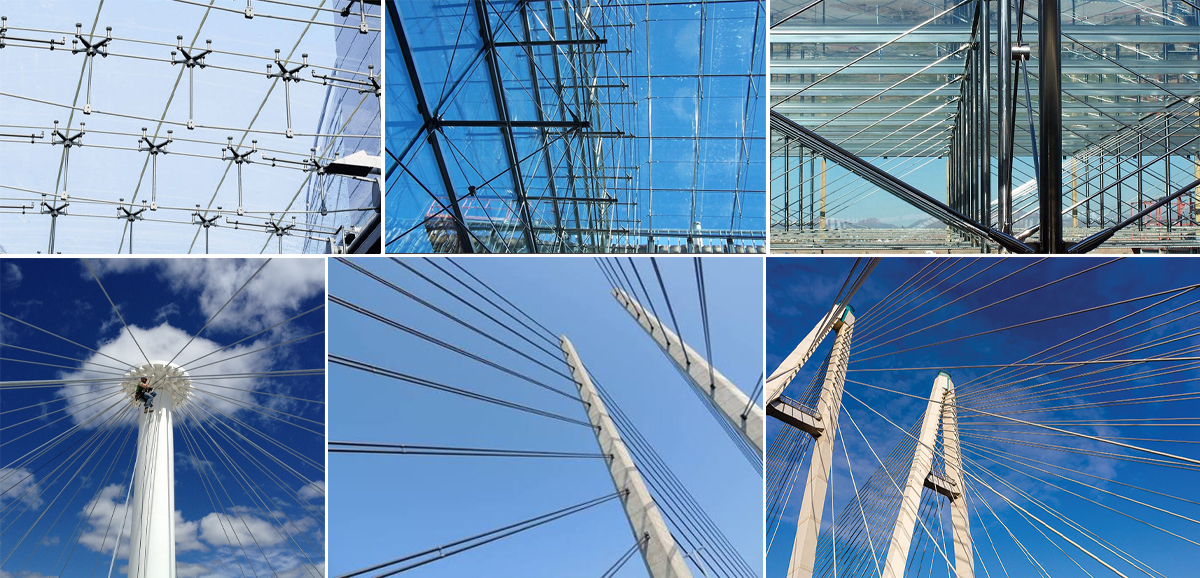
Steel Cable Structures use high-strength cables, rods or tension members to support roofs, façades, bridge decks or canopies.
Common systems include:
Cable-stayed roofs
● Suspended roofs
● Cable-net structures
● Mast-and-cable canopies
● Tension-ring stadium roofs
● Cable-supported glass façades
● Cable-stayed bridges
● Membrane roofs supported by steel cables
● Hybrid arch-and-cable systemsCable structures can reduce the quantity of heavy compression members and create slender, visually open structures. However, they require precise control of geometry, pretension, support stiffness, movement and erection sequence. Cable-stayed roofs, cable nets and suspended systems are recognised forms of steel tension structures.
| Overall Length | Approx. 100 m |
| Maximum Projection | Approx. 25 m |
| Structural System | Steel masts with radial cables |
| Roof Material | Lightweight metal or tensile membrane |
| Main Use | Stadium, terminal or exhibition entrance |
| Columns | Positioned outside the main pedestrian zone |
| Drainage | Integrated edge drainage |
| Lighting | Suspended from secondary steelwork |
| Installation | Masts, boundary steel, cables and roof installed in sequence |
| Key Control | Cable pretension and final roof geometry |
The installation process may require temporary supports and staged tensioning so the final geometry matches the approved structural model.
● Cable layout
● Mast positions
● Pretension force
● Support stiffness
● Roof self-weight
● Wind suction
● Rainwater ponding
● Temperature movement
● Dynamic response
● Fatigue
● Connection detailing
● Tensioning sequence
● Long-term inspection accessCable-supported stadium roofs demonstrate that steel compression rings, cables and lightweight roof systems must be designed and installed as one coordinated system.
The selection should be based on the project’s main functional and engineering priorities.
| Economical single-storey warehouse | Portal frame |
| Warehouse with heavy cranes | Heavy rigid frame or truss |
| Multi-storey office or hotel | Braced or moment steel frame |
| Wide exhibition hall | Space frame or long-span truss |
| Column-free bulk storage | Arch truss or curved space frame |
| Pedestrian crossing | Steel girder, truss, arch or cable-stayed bridge |
| Stadium canopy | Cantilever truss, space frame or cable-supported roof |
| Lightweight architectural canopy | Mast-and-cable or tension structure |
| Large curved roof | Arch, lattice shell or curved space frame |
| Complex landmark project | Hybrid steel structural system |
A complex project may combine several systems. A stadium may use concrete seating bowls, steel trusses, cable systems and space-frame entrance structures within the same development.
A price should not be calculated from floor area alone.
To prepare a meaningful steel structure proposal, the buyer should provide:
● Country
● City
● Site altitude
● Coastal or inland environment
● Local design code● Warehouse
● Factory
● Bridge
● Stadium
● Office
● Storage shed
● Transport terminal
● Commercial or public building
● Length
● Width
● Height
● Clear span
● Number of floors
● Column spacing
● Wind speed
● Snow load
● Seismic requirements
● Floor loads
● Roof equipment
● Crane capacity
● Suspended loads
● Vehicle or pedestrian loads
● Roof panel
● Wall panel
● Insulation
● Skylights
● Doors
● Windows
● Ventilation
● Fire-rated walls
● Soil report
● Foundation information
● Truck access
● Crane access
● Local installation labour
● Transport limitations
Without these details, a price per square metre is only a preliminary marketing figure and cannot represent the final structural solution.
The intended use, dimensions, site conditions and design standards are confirmed.
Portal frame, truss, frame, space frame, arch or cable system is selected according to span, load and architectural requirements.
The preliminary column grid, structural depth, support positions and building envelope are coordinated.
The project-specific load combinations, structural stability, deflection and connection forces are calculated according to the selected design standard.
Column loads, anchor-bolt forces and support reactions are supplied for foundation design.
Bolted, welded and special node connections are designed.
Fabrication drawings, member numbers, plates, holes, welds and bolt specifications are prepared.
The client or project engineer approves the drawings before steel cutting begins.
Special structures such as bridges, stadiums, arches and cable systems may require specialist engineering review and independent checking.
The fabrication process can include:
● Material receipt and traceability
● Plate and profile inspection
● CNC cutting
● Drilling
● Edge preparation
● Beam and column assembly
● Welding
● Dimensional inspection
● Non-destructive testing where specified
● Trial fitting of complex connections
● Surface preparation
● Painting or galvanizing
● Member numbering
● Packing and loading
The level of inspection must be defined by the project specification.
Complex space-frame nodes, bridge segments, stadium trusses and cable anchorage assemblies may require trial fitting before shipment.
A project-specific inspection plan can include:
● Steel grade
● Material certificates
● Plate thickness
● Profile dimensions
● Bolt specifications
● Welding consumables
● Member dimensions
● Hole positions
● Cutting quality
● Weld appearance
● Weld size
● Connection plates
● Member straightness
● Truss geometry
Depending on the project requirements:
● Visual inspection
● Ultrasonic testing
● Magnetic-particle testing
● Dye-penetrant testing
● Radiographic testing
● Welding-procedure records
Trial assembly may be used for:
● Bridge sections
● Large stadium trusses
● Space-frame nodes
● Arch segments
● Cable anchorage steelwork
● Complex architectural steel
● Surface-cleanliness grade
● Primer thickness
● Intermediate-coat thickness
● Top-coat thickness
● Galvanizing thickness where specified
● Repair of damaged coating
● Member identification
● Bolt and accessory boxes
● Packing list
● Installation sequence
● Protection of machined surfaces
● Moisture protection
● Container or break-bulk loading planCustomers may request production photos, inspection records, trial-assembly photos, coating reports, packing photos and loading records according to the project agreement.
Available project documents may include:
● Design-basis report
● General-arrangement drawings
● Structural calculations
● Foundation-reaction drawings
● Anchor-bolt pla
● Shop drawings
● Connection drawings
● Fabrication drawings
● Bill of materials
● Bolt list
● Welding documentation
● Coating specification
● Inspection and test plan
● Packing list
● Container-loading plan
● Erection drawings
● Installation sequence
● Maintenance recommendations
The exact document package depends on whether Huisheng supplies only fabricated steel components, a complete building package or broader engineering and installation support.
The transportation method depends on member size and project location.
Available methods may include:
● Standard containers
● Open-top containers
● Flat-rack containers
● Break-bulk shipping
● Road trailers
● Project cargo vessels
Long trusses, arches, box girders and stadium components may need to be divided into transportable segments.
The segment design should balance:
● Container length
● Road limits
● Port lifting capacity
● Number of field connections
● Site crane capacity
● Assembly space
● Fabrication accuracySmaller components should not be created only to fit a container if the resulting number of site connections increases cost, risk and installation time excessively.
A typical erection sequence may include:
Special structures require additional procedures.
A bridge may require launching, segment lifting or temporary piers. A stadium roof may be assembled at ground level before lifting. A space frame may be assembled in blocks. An arch may require temporary support until the structural system is closed. A cable roof requires staged pretensioning.
The appropriate protection depends on the environment.
Available systems may include:
● Shop primer
● Multi-layer paint system
● Epoxy coating
● Polyurethane top coat
● Hot-dip galvanizing
● Metallizing
● Weathering steel where appropriate
● Fire-protection coating
● Intumescent coating
● Encasement or board protection
Projects near the sea, chemical plants, fertilizer storage or high-humidity environments require more detailed corrosion assessment than a dry inland warehouse.
Bridge corrosion protection also requires attention to drainage, water traps, inaccessible joints and future maintenance.
The current page should not present From $87 without identifying the unit and included scope. A safer website expression is:
Custom quotation based on approved dimensions, loads, materials and project scope.
The final price depends on:
| Structural System | Portal frame, truss, space frame, arch or cable |
| Building Size | Total area and building height |
| Clear Span | Longer spans normally require deeper or heavier structures |
| Design Loads | Wind, snow, seismic, cranes and equipment |
| Steel Grade | Material strength and local standards |
| Connection Complexity | Standard bolts or special welded nodes |
| Fire Protection | Required fire-resistance period |
| Corrosion Protection | Paint, galvanizing or specialist coating |
| Roof and Wall System | Cladding, insulation and glazing |
| Fabrication Tolerance | Standard building or bridge/stadium precision |
| Trial Assembly | Required for complex or critical structures |
| Shipping | Container, flat rack or break-bulk |
| Installation | Local labour, cranes and temporary works |
A warehouse shell, a bridge girder and a cable-supported stadium roof cannot be compared using one universal square-metre price.
The project location, dimensions, function, design loads, local code, cladding, equipment, crane requirements, fire requirements and installation conditions are required.
Project-specific solutions can include warehouses, frames, bridges, trusses, space frames, arches and cable-supported structures. Specialist structures require appropriate engineering scope and local approval.
The design basis can be prepared around the required code and project data. Final compliance, professional stamping and approval must be coordinated with qualified professionals in the destination country.
There is no single maximum span for all systems. Portal frames, trusses, space frames, arches and cable systems provide different span capabilities. The correct solution depends on loads, structural depth, budget and transport conditions.
Yes. Crane capacity, hook height, duty classification, runway position and operating requirements must be supplied before design.
Steel bridge components and prefabricated bridge systems can be supplied according to approved bridge drawings and specifications. Bridge engineering and authority approval must be clearly assigned within the contract.
Yes, subject to project-specific engineering, node design, fabrication capability, transportation planning and erection procedures.
Many warehouse and frame structures can be prepared for future horizontal or vertical expansion. Expansion connections must be included in the original engineering design.
They can be included, but the quotation must clearly identify panel type, thickness, insulation, colour, flashing, gutters, doors and windows.
Foundation reactions and anchor-bolt information can be supplied. Local foundation construction is normally completed according to the geotechnical report and locally approved foundation design.
Small and medium components can be shipped in containers. Oversized trusses, arches, bridge girders and stadium components may require flat-rack or break-bulk shipping.
Installation drawings, erection sequences, packing lists and remote technical guidance can be included. On-site supervision depends on the project location, scale and service agreement.
Production time depends on drawing approval, steel quantity, fabrication complexity, coating, trial assembly and project schedule. A fixed lead time should only be confirmed after the approved bill of materials is available.
Service life depends on structural design, environment, corrosion protection, fire protection, drainage, inspection and maintenance. It should not be represented by one universal number for every project.
Only the items expressly listed in the formal quotation are included. Product fabrication, cladding, packing, freight, foundation, cranes and installation should be separated clearly.
At Huisheng, we believe that professional focus creates trusted quality.
 +86 17563695938
 contact@hshouse.com
 No. 1099, Gongye 1st Street, Weicheng District, Weifang City, Shandong Province, China



View on Mobile
Copyright © 2026 Huisheng International Trade All rights reserved
Send us your requirements. Free custom floor plan or 3D design in 3 working days
Submit form